The IP monitoring diagram is a graphical representation of the electrical, optical, and mechanical connections between individual devices in a monitoring system. This diagram provides information about cable types, lengths, connection methods, and the devices involved in the IP surveillance system.
What does an IP monitoring diagram include? What are its components?
An IP monitoring diagram includes information about the entire installation, including:
- Cable types
- Cable lengths
- Plugs and sockets
- Connection methods between the recorder and cameras
- Locations of individual devices
- Types of active and passive devices
Additionally, an IP monitoring diagram may include information about network interfaces and the configuration of network equipment required to set up and manage the surveillance system.
PoE camera power supply diagram
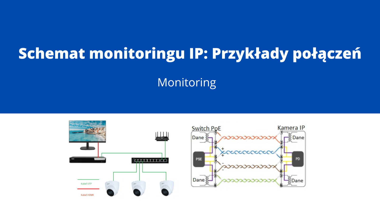
The PoE camera power supply diagram is an integral part of the IP monitoring diagram. It illustrates the connection method between cameras and the recorder or PoE power supply. The diagram provides information about the cable type, connection length, plug/socket, and camera power supply method.
Diagram of IP monitoring camera connection.
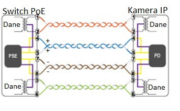
IP Camera Connection Diagram
The IP camera connection diagram provides information about the connection of the IP camera to the local network, routers, access points, switches, and other devices. It may include details about the cable type, connection length, and the method of connection. This diagram can be used to determine optimal camera connection solutions to ensure efficient monitoring.
Single-Family Home IP Monitoring Diagram
The connection diagram for a single-family home monitoring system equipped with IP cameras, an IP recorder, a router, PoE switch, and a monitor.

IP Camera Connection Diagram to NVR
The IP camera connection diagram to an NVR (Network Video Recorder) provides information about the connections between the cameras and the monitoring management devices.
The diagram includes details about the cable type, connection length, plug/socket, and camera power supply method.
Open this in UX Builder to add and edit content
IP Camera Connection using Ethernet Cable
The primary cable used in IP camera connections is commonly referred to as an Ethernet cable. This type of cable enables data transmission and video signal delivery to the IP recorder.
The most commonly used type of Ethernet cable in IP monitoring is UTP (Unshielded Twisted Pair) Cat5e or Cat6.
Connection Diagram for RJ45 to Camera, How to Connect?
The connection diagram shows how to connect a computer cable to an RJ45 plug.
The T-568B standard, commonly used in Poland, specifies the order of wire connections as follows:
White-Orange Orange White-Green Blue White-Blue Green White-Brown Brown
Make sure the pin arrangement on the plug matches the sequence above, with the clip at the back.
Repeat the same process for the other end of the cable.
T-568B Standard

